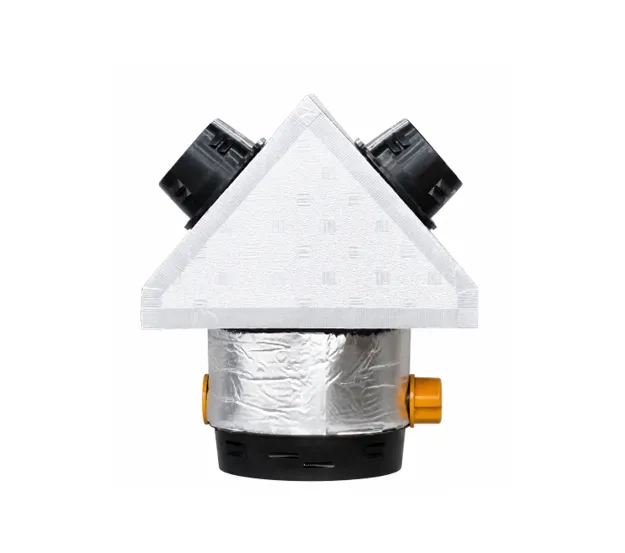
The Sunco Duct 1ZANT-35-2X25 is a CNC-manufactured insulated distribution box with one 350mm motorised inlet supplying two 250mm outlets as a single zone.
Its precision-mitred body is manufactured from 21mm foil-faced PIR ductboard, delivering a calculated material rating of R0.95.
Comparable EPP products generally require approximately 40mm thickness to approach R1.0- worth checking when assessing R-value claims on thin moulded boxes. Foamed rotomoulded LLDPE fittings may require approximately 25–35mm to reach R0.4, depending on foam density, consistency and verified thermal conductivity.
While R0.4 may satisfy minimum requirements in some applications, higher thermal resistance provides greater protection against surface condensation in Queensland’s hot, humid roof spaces—helping prevent coffee-coloured ceiling stains and costly callbacks.
Pair it with our Australian made 4-Zero R1.5 Flexible Duct for a high-performance thermal installation designed for Queensland conditions.
Custom spigot and motorised zone-outlet configurations are available in 200mm, 250mm and 300mm sizes. Hit us up and we can make it happen!
Fast Clip-In Installation - No tools required!
The compact ANT body fits through most larger return-air grille openings before its fittings are installed.
Each 200, 250, 300mm zone motor and spigot fits through the opening of the round diffuser. The flexible duct can be taped to the spigot below the ceiling, passed into the roof space and clipped directly into the ANT body.
Features
- Two 250mm outlets controlled as one zone
- 1 × 350mm clip-in zone motor
- 2 × 250mm clip-in outlet spigots
- 350mm zone-motor cable included
- Graphene foam seal on every clip-in connection
- CNC-cut, precision-mitred PIR construction
- Compact roof-space installation
- Less taping and assembly in confined spaces
Specifications
| Specification | Details |
|---|
| Product Code | 1ZANT-35-2X25 |
| Configuration | One zone supplying two outlets |
| Body | 21mm foil-faced PIR ductboard |
| Body Size | 400 H to apex × 580 W × 420 D mm |
| Thermal Conductivity | 0.022 W/m·K |
| Calculated Material R-Value | R0.95 m²·K/W |
| Inlet | 1 × 350mm clip-in zone motor |
| Outlets | 2 × 250mm clip-in spigots |
| Indicative Airflow* | 300–400 L/s |
| Indicative Balanced Outlet Airflow* | 150–200 L/s each |
| Maximum Recommended Airflow | 500 L/s total |
| Maximum Balanced Outlet Airflow | 250 L/s each |
| Zone-Motor Cable | Included |
| Connection Seals | Graphene foam |
1Z = one controlled zone · ANT = insulated box body · 35 = 350mm inlet · 2X25 = two 250mm outlets
*Indicative airflow assumes two balanced ANT boxes connected to separate supply-air paths, each using up to 6m of fully extended 400mm flexible duct. Outlet figures assume all four outlets are open and connected through up to 6m of fully extended 250mm flexible duct. Actual airflow depends on fan capacity, available static pressure, duct compression, bends, terminal resistance, balancing and commissioning.
Thermal figures are calculated material values. Finished thermal performance depends on verified material properties, sealing and installation.